1.0 PROBLEM
A reliable, low-cost sleep aid that uses environmental automation — scent diffusion and a graduated alarm — to cue sleep onset and wake-up without jarring the user from sleep.
2.0 ARCHITECTURE
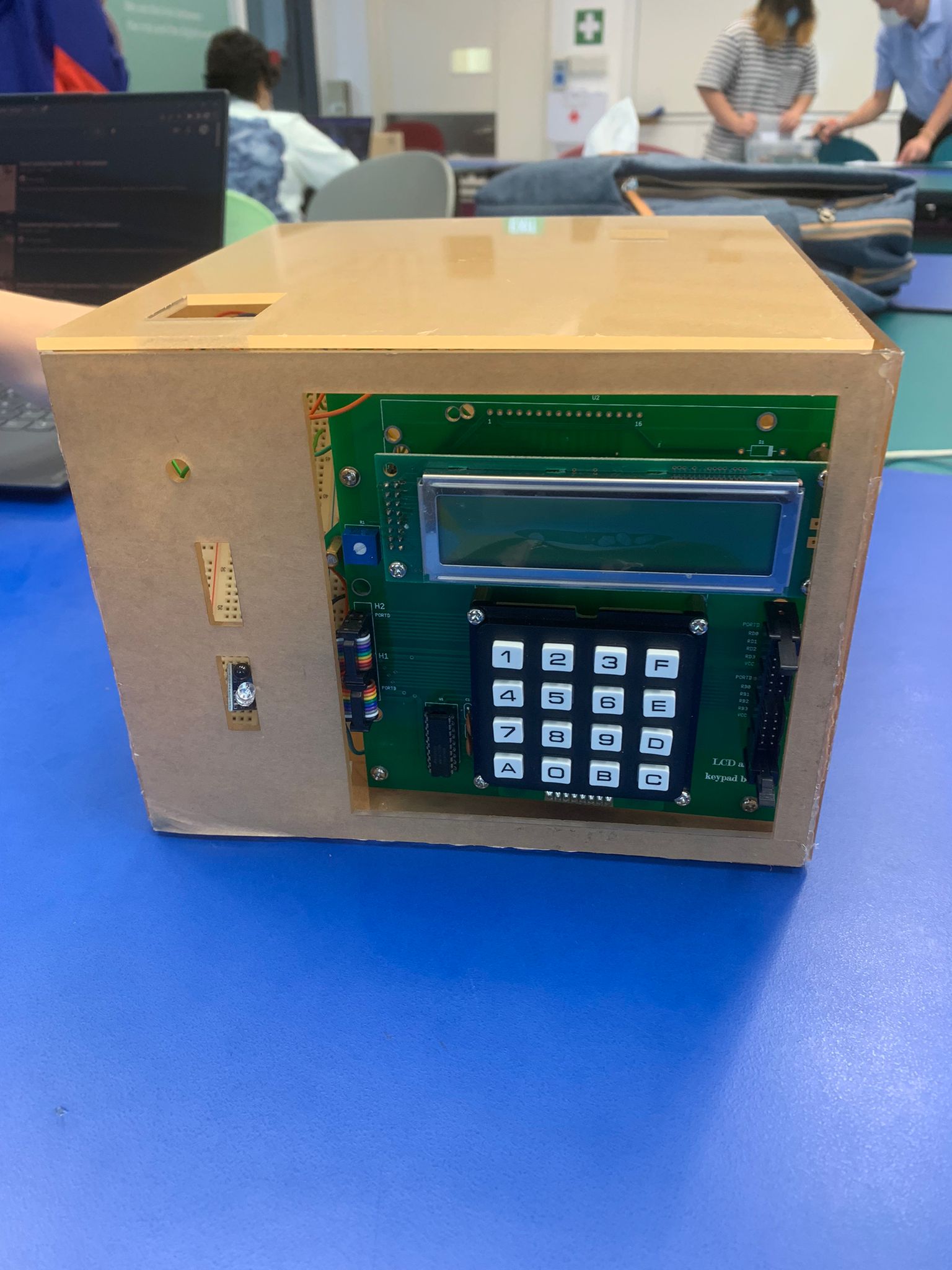
Time is tracked by a software RTC implemented via a Timer0 interrupt service routine. The DS1307 hardware RTC provides persistent timekeeping across power cycles: it is read on boot via I²C and the value is handed off to the software RTC for interval counting. This dual-RTC approach eliminates continuous hardware polling while maintaining real-world clock synchronisation.
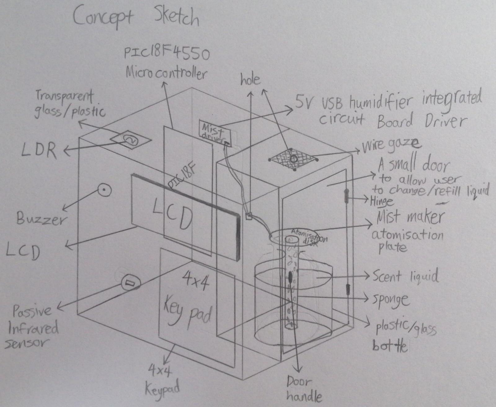
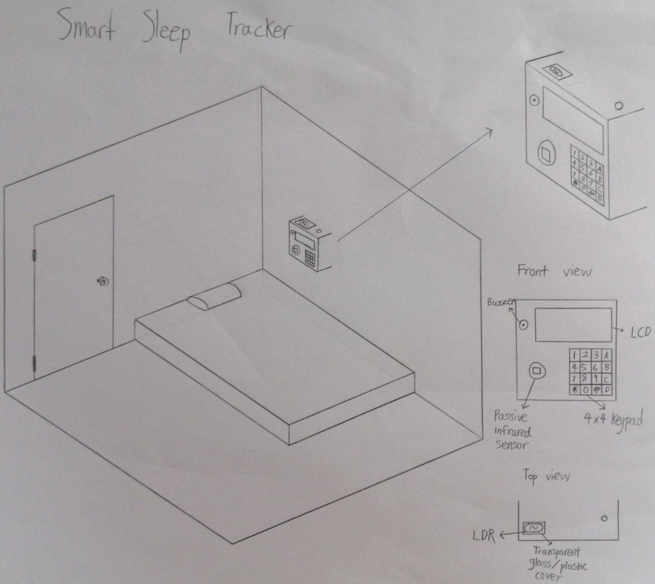
Activation requires two simultaneous sensor conditions: the PIR detects the user in bed, and the LDR confirms ambient darkness. Both conditions must be true to trigger the aromatherapy diffuser via the USB control line — single-sensor activation would cause false triggers.
The wake alarm uses a five-stage escalation. After each stage the ISR checks whether the PIR still detects in-bed presence. If the user has risen, the sequence terminates. If not, it escalates to the next stage, preventing the alarm from being slept through while allowing genuine early rising to silence it immediately.
3.0 ERRATA & REVISIONS
Working in bare-metal C without an OS makes explicit everything that higher-level frameworks abstract away: interrupt latency, register-level peripheral configuration, the exact clock cycles each instruction costs. There is no garbage collector, no exception handler, no scheduler — you get exactly what you write.
When I later built AidBuddy’s RAG pipeline — tuning chunking strategies, retrieval parameters, and inference constraints — I found myself reasoning in the same terms: latency budgets, resource limits, state transitions between pipeline stages. The vocabulary changed; the engineering mindset did not.
If revisiting this project, I would separate peripheral drivers from application logic with a hardware abstraction layer. This would make the firmware portable across PIC18 variants and testable in software simulation without a physical board — neither was possible in the original, where peripheral register access was scattered throughout application code.